This is my HF amplifier that I use, which I put together in my garage. I did spend some money and took some time to get it all together, but the end result is WORTH IT!
For one thing, I get the satisfaction of operating home made equipment, and this unit also does not require ALC, as during normal operation, the transistor never gets to it’s P1dB point of 300W. At most, it will get to 289W (as calculated – real world results seem to match).
I did this by including an attenuator on the input side of the amplifier, which allows me to drive the amplifier with 10W of RF on any of the HF bands. I didn’t bother including a pre-amplifier, as these tend to be almost useless on HF anyway.
The ALC in the radio keeps the drive level at 10W or less, so the end result is, no ALC needed in the amplifier. The 2 tone test on this amplifier went very well, and the harmonic suppression is just over 50dBc (depending on the band, it varies, but is always just over 50dBc.)
Overdriving your amplifier causes splatter – no overdrive, no splatter.

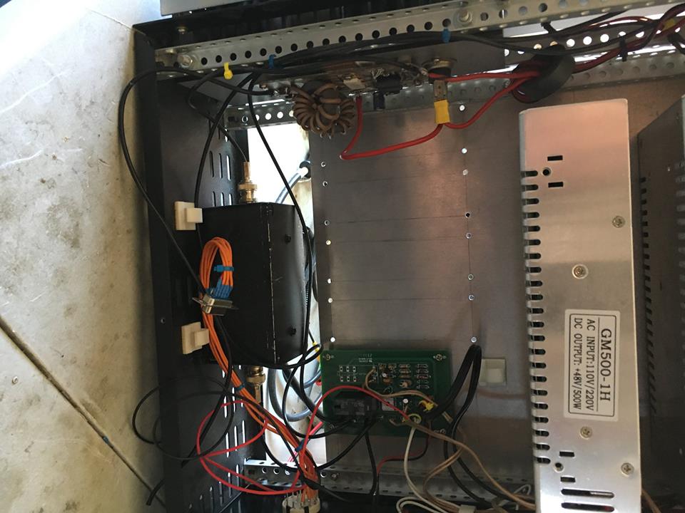
The black box to the left is my home built attenuator, 11.8dB turns 10W of drive into just under 1W which is all that is required to make full output on this amplifier.

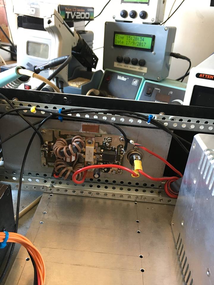
This is the PA board, with the main device being an NXP MRFE6VP6300H.
This transistor will tolerate full output into an open circuit or short circuit for a limited amount of time without degradation in output. The device is secured to a large fan cooled heatsink with a copper spreader fitted. In the event of an antenna failure, during TX, the device may dissipate up to 900W of thermal energy, so a good heatsink is a must! To the right of the PCB is a thermal cutout that will remove the supply from the PA if the heatsink gets to 50 degrees C.
MRFE6VP6300H

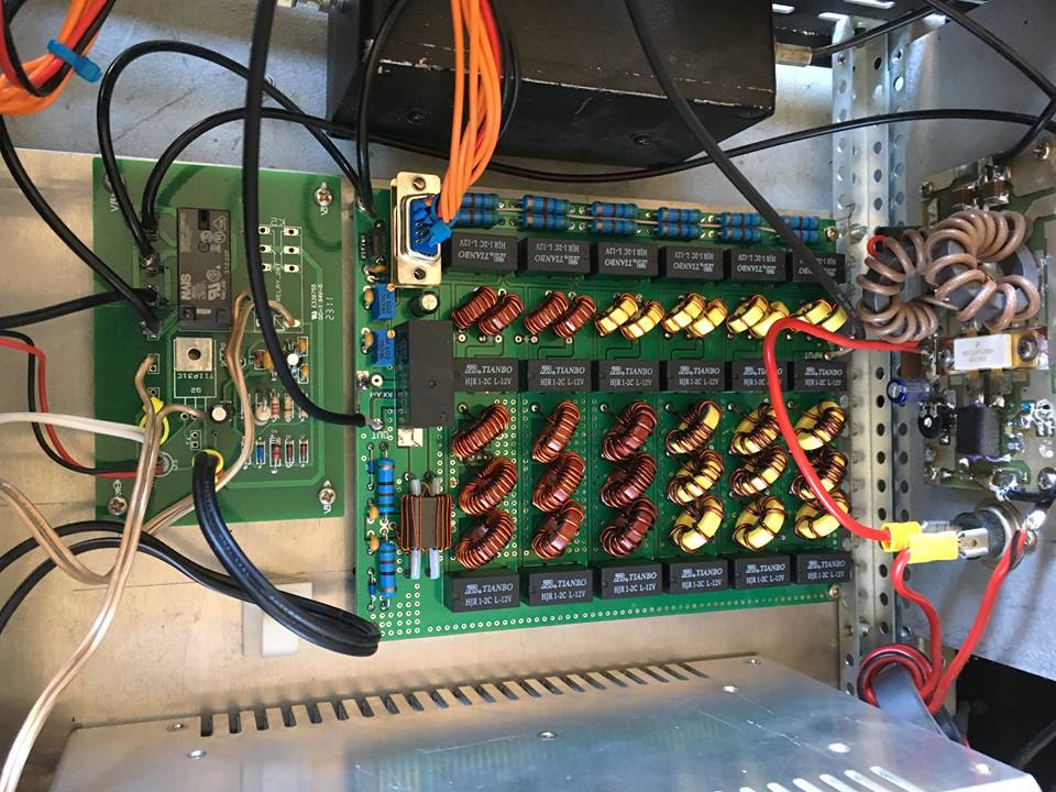
This is the RF deck of the amplifier, with the PA to the right, LPF array and RF trigger next to it, and the 11.8dB attenuator at the top.
I’ll add more photos later, but for now, you get the idea.
73 from VK2TIM!